


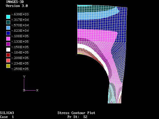
Plot of nodal or peak principal stresses (psi) in the radial (X) direction superimposed on the deflected shape (in.) scaled up by a factor of 50. Note that all the stresses are compressive.
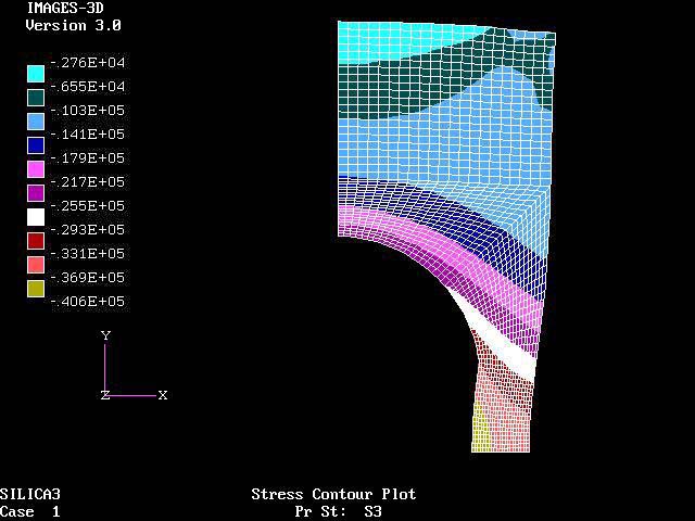
Plot of nodal or peak principal stresses (psi) in the hoop (Z) direction superimposed on the deflected shape (in.) scaled up by a factor of 50. Note that all the stresses are compressive
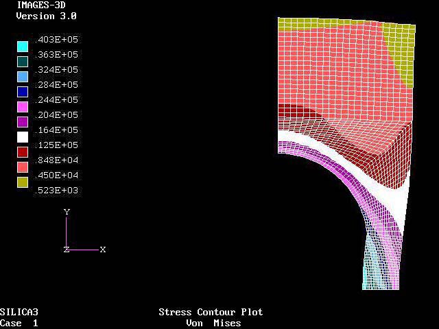
Plot of Von Mises effective stresses (psi) superimposed on the deflected shape (in.) scaled up by a factor of 50.
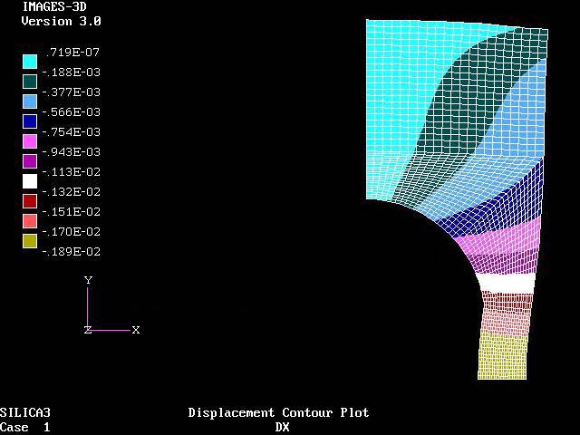
Plot of radial (X) displacements (in.) superimposed on the deflected shape (in.) scaled up by a factor of 50.
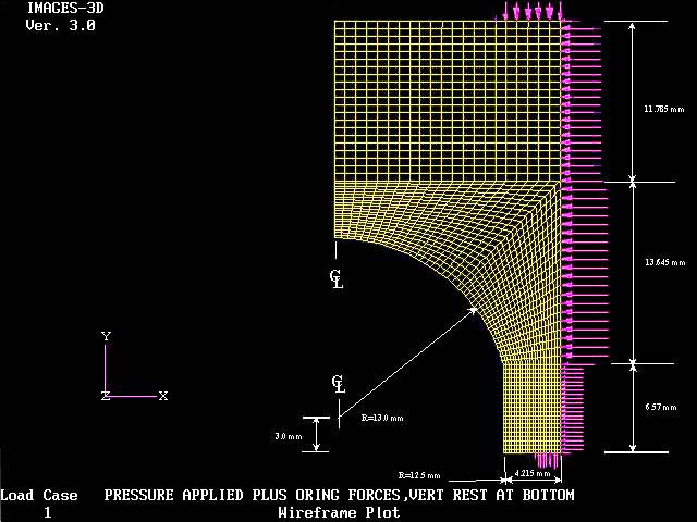
NOTE: The size of the arrow indicates the force per node which is based on the width of the adjacent element faces on which the pressure is applied and the magnitude of the applied pressure or force.
A pressure force of 10000 psi has been applied along the longitudinal outside edge of of the lens and on the top and bottom surfaces up to the centerline of the O rings. In addition, O ring forces of 50 #/radian and 30 #/radian have also been applied in the area of the O ring grooves at the top and bottom edges respectively.
This finite element lens model is made up of 4 generated blocks with each block, 21 elements by 21 elements for a total of 1870 nodes and 1764 elements. The element size in the lowest and most critical section is .2mm by .3mm.
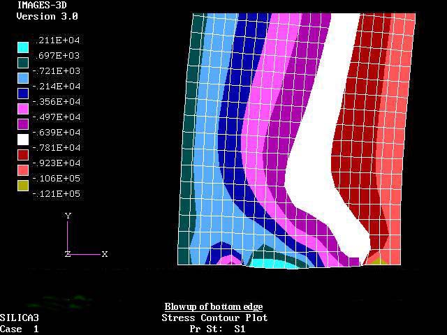
Plot of nodal or peak principal stresses (psi) in the longitudinal (Y) direction superimposed on the deflected shape (in.) scaled up by a factor of 50. The bottom edge is free to move inward radially (X), but is restrained longitudinally except in the area of the O ring groove. The top edge is not restrained in any direction. Note the small tension stress in the unsupported area of the O ring groove at the bottom edge, on the outside about 2/3 to 3/4 ths of the way up in this blowup and all around the inner edge of the hogged out portion of the lens.
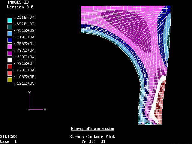
Plot of nodal or peak principal stresses (psi) in the longitudinal (Y) direction superimposed on the deflected shape (in.) scaled up by a factor of 50. The bottom edge is free to move inward radially (X), but is restrained longitudinally except in the area of the O ring groove. Note the small tension stress in the unsupported area of the O ring groove and all around the inner edge of the hogged out center of the lens.

NOTE: Plot of nodal or peak principal stresses (psi) in the longitudinal (Y) direction superimposed on the deflected shape (in.) scaled up by a factor of 50. The bottom edge is free to move inward radially (X), but is restrained longitudinally. The top edge is not restrained in any direction.